
After Einstein and his introduction of the Theory of Relativity, it was generally thought that objects moving at relativistic speeds (close to the speed of light) would appear contracted, or squashed, in the direction of motion. It wasn't until decades later, with the publications in 1959 by Roger Penrose and James Terrell, that it was understood that an object approaching an observer at relativistic speeds would actually appear elongated, and even appear to rotate, allowing the back side of the object to be 'viewed' before the object had arrived. Only when receding from the observer does that fast-moving body appear squashed.
Though the effect is real, in actuality it cannot be observed visually, since the object would be moving by at unimaginable speed. Unless of course the moving object was vastly large, in which case we could indeed observe this phenomenon. It does seem unlikely that we will have any solar-system-sized objects moving by us at 0.99 the speed of light anytime soon, however. At least I hope not.
When I first read about this effect, I thought it would be interesting to work out my own equations to graphically describe the effect. First it is necessary to understand why this rotation effect happens in the first place.
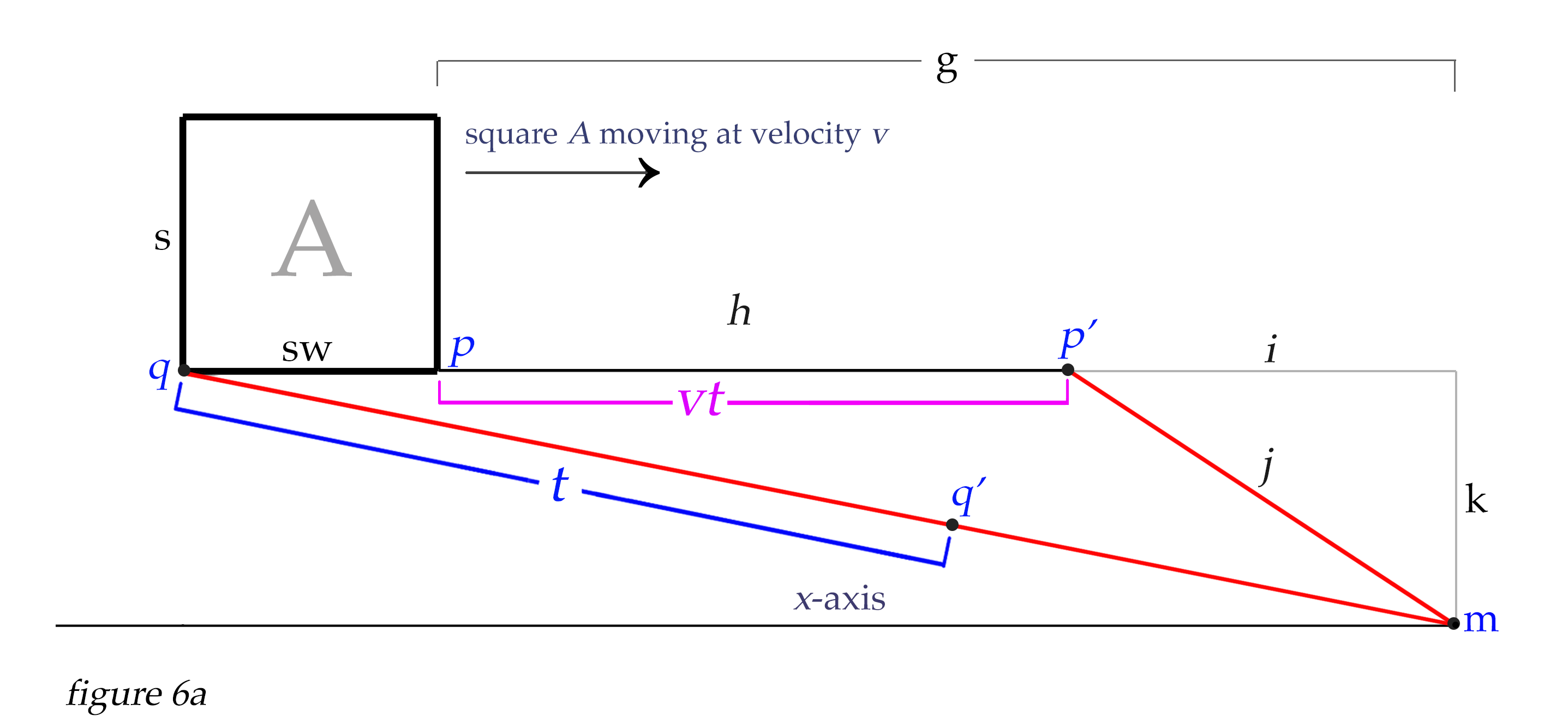
Let's imagine a 2D world, and you (the observer) are sitting at point m. Let's think of a square A that is 1 kilometer in length and height. Let's place the square 10 kilometers away from you to the back face (distance d), 9 km away from the front face (distance g), and the bottom face of the square is one kilometer above the earth (we'll call this distance k). If it were moving it would come straight at you and pass right over your head one kilometer above. But for now, let's give it a velocity of v = 0, so it isn't moving at all, just hovering there, its bottom face 1 km from the ground. We are speaking of the distance along the ground to the front and back faces of the square, which is along the x-axis.

To begin to understand the basics of what is happening, we will only look at the bottom of the object at first. Let's look at the path of light from corner α (back bottom corner of square in figure 2) to point m, which is you, the observer. We will call this starting point of light point q, making a line between q and m. At this moment point q and corner α have the same coordinates, but this will not always be so when the square is moving. So we will consider the line qm.
Point m is at x = 0, and the length along the x-axis from point m to point q we will call d for distance. So the path that light will travel from point q to point m is actually the hypotenuse formed by the triangle dkh, and we can find length h using the pythagorean theorem: \(\sqrt{d^2 + k^2} = h\). So h is line qm.
Similary, since g is the distance along the x-axis from point p to the observer at point m, we can find the length of the path light will take from point p to point m as \(\sqrt{g^2 + k^2} = j\). So j is line pm.
Clearly the distance light travels to us from point p is a little shorter than the distance light travels to us from point q. Now imagine that we have an insanely fast camera with a shutter speed as quick as 1/100 millionth of a second or so, allowing us to take a very fast snapshot of the square from point m. The photons arriving to our position from point q have left point q at an earlier time than the photons arriving to us from point p. The difference in time between the departure of photons from each point that will simultaneously arrive to point m is (h - j)/c. This shows that the light from point p departed 0.00000325 seconds later than the light from point q, to arrive simultaneously to our position as we take the snapshot.

Now we get to the reason for all this detail, which at first seems unnecessary. Here's the thing - because the object has a velocity of zero, the square has not moved at all in the time it takes light to travel from point q to point m. But if the square is moving, then while the light is traveling to us from point q, then point p is also moving toward us during the time it take the light to move from point q to point m. This is the very situation which causes the object to appear to stretch and rotate as its speed increases, as our very fast snapshot would begin to show at very high velocities. This is what we call Terrell rotation, or the Terrell-Penrose effect. Let's explore this.
Clearly, light moves so fast that this effect would not even begin to be noticeable until the velocities approach a significant percentage of the speed of light. Let's ramp up the speed of the object to v = 0.99c, or 99% of the speed of light. Now things begin to get interesting. So imagine this - a photon reflects from point q when corner α of the square is exactly 10 km away (along the x-axis). Now, while that photon is making a straight line to point m at the speed of light along line h, the other bottom corner p of the square is also moving at 0.99c, almost as fast as the light. If our snapshot is taken exactly when the photon from point q arrives to us at point m, then the question is this: What will the coordinates of corner p have to be to send a photon to us that arrives simultaneously with the photon from point q? The answer is not intuitive, and we need to solve it algebraically to find the answer. But first let's visualize the problem with some geometry.

As the photon travels from point q toward the observer at point m, we will let t equal Δq, or the distance the light travels from point q to any point q' along the line h. Similarly, as the photon is moving from q to q' with distance t, the corner of the square at point p is also moving parallel to the x-axis from point p to p'. The distance Δp traveled by the square from point p to p' is velocity * t. Since our square for this example is moving at v = 0.99c, then the distance from p to p' is vt, or 0.99 * t.
Our quest right now is to find the conditions where the observer's snapshot captures both the photon from point q, and also the photon from point p' that will arrive at the same exact instant. Notice that from any point p', a photon would follow hypotenuse j of unique length found by \(\sqrt{(g - vt)^2 + k^2}\). The conditions that need to be met to allow the photons from q and p' to arrive simultaneously are when \(h - t = j\). Remember that h = the hypotenuse described by line qm, and j = the hypotenuse described by line p'm. Since all of line h represents the distance traversed at speed of light, and j also represents the distance traversed at the speed of light, it is clear that \(h - t = j\). The problem to be solved is to find the exact distance the square has moved from p to p' that will satisfy our conditions. And to find this unique solution we can do some algebraic manipulation to create a quadratic equation for that purpose.
We know that only when \(h - t = j\) are the precise conditions met where the light from both q and p' will arrive to us at m simultaneously. We also know that the distance Δp from p to p' always equals vt. And looking at figure 3 above, we see that \(i = vt - g\) (we will consider the value of i to be negative here, because it is moving along the x-axis backward from zero along the negative number line). Now we can construct an equation that will allow us to solve for i, thereby giving us the location of the square's corner at point p' that will appear to us on our snapshot, revealing the Terrell-Penrose effect of the elongated positions of the bottom corners of the square.
Let's manipulate the equations above to get to our quadratic equation that will solve for i. Since
\[h - t = j\]
we can also write that as
\[h - t = \sqrt{i^2 + k^2}\]
Let's consider the value of i to be the distance from n to p'. In figure 3 we see that this will result in a negative value for i. With this in mind we can say
\[vt = g + i\]and
Since
then
which leads to
Creating a quadratic equation from this to solve for i would be as follows:
\[vh - g - i = v\sqrt{i^2 + k^2}\] \[((vh - g) - i)^2 = v^2(i^2 + k^2)\] \[(vh - g)^2 - 2i(vh - g) + i^2 = v^2i^2 + v^2k^2\]
multiply both sides by \(\frac{1}{i^2}\)
\[\frac{(vh - g)^2}{i^2}\ - \frac{2(vh - g)}{i}\ + 1 = v^2 + \frac{v^2k^2}{i^2}\] \[\frac{(vh - g)^2 - v^2k^2}{i^2}\ - \frac{2(vh - g)}{i}\ + (1 - v^2) = 0\] \[((vh - g)^2 - v^2k^2)\frac{1}{i^2}\ - 2(vh - g)\frac{1}{i}\ + (1 - v^2) = 0\]
Now we see we have created a quadratic equation in which we can solve for i:

Figure 4a
Even though the quadratic coefficient a, the linear coefficient b, and the constant c are all comprised of equations instead of simply constants, we can still solve the quadratic in this form. Noting that the variable is in reciprocal form, we will take the reciprocal of the quadratic formula to solve for i:
All moving objects experience relativistic length contraction along their line of motion. As we can see from the graph below, this effect is not noticeable until an object is moving at a significant percentage of the speed of light. At speeds we experience on earth, this effect is not apparent at all. For example, a jet flying at mach 1 (the speed of sound, or about 1,235 km per hour) would only contract to 0.99999163 of its rest length. For a jet 20 meters long, this would only be a contraction of 0.1674 millimeters. Even if it were moving at half the speed of light, or 0.5c, it would only have contracted to 0.866 of its rest length.
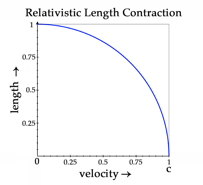
Figure 4b
We haven't yet considered the effect of relativistic length contraction on our moving square A. Since our square will be contracted along its line of motion, we have to calcuate the length of the square along the x-axis with length contraction included. Length contraction is simply calculated as
\[L = L_0\sqrt{1 - \frac{v^2}{c^2}}\]
Where \(L_0\) is the length of the object at v = 0.
We can dispense with division by \(c^2\) since we are letting \(c = 1\), and calculate the length of the square's sides thus:
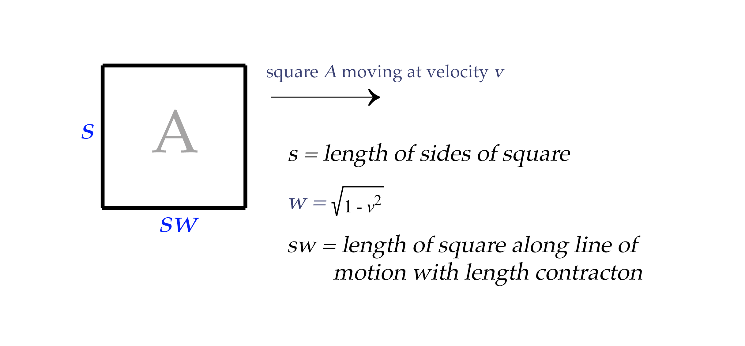
Figure 4c
And since the square is 1 km long on each side, multiplying the top and bottom lengths with the length contraction formula gives us \(1 * \sqrt{1 - 0.99^2}\), or 0.141067 km for the length of the square. Which would give the square dimensions more like this:
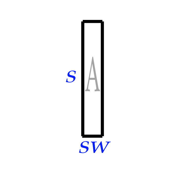
Figure 4d
So with these parameters in mind, we can now insert the corrected distances to the front face of the square into our quadratic equation. This will increase the value of g to |qx| - sw (understanding that the absolute value |qx| equals the distance d to the back face of the square along the x-axis). We will leave the initial position of the back corner of the square (point q) the same, and let the length contraction be represented by the coordinates of the square's front face.
Now when we solve for i, the result is i = -3.79 km. This means when the far corner of the bottom face at point q is 10 km away, our snapshot would show the near corner p to be located at p', stretched out to only 3.79 km away from us at point m (as measured along the x-axis). This means the bottom face of square A, though in reality being contracted in length to sw or 0.14 km while moving at v = 0.99c, would show its apparent length on our snapshot as 6.21 km in length! This is the Terrell-Penrose effect, or Terrell rotation. We'll see the rotation effect better when we move up our calculations from a line into two and then three dimensions.

We now have the tools to calculate the effect in a 2-D coordinate system. With our point q fixed at the location of far bottom corner of square A at given moment in time, we can scan with our quadratic equation along the lines comprising the four faces of the square, in relation to the fixed position of point q. Remember that point q represents the point from which light leaves the coinciding point on the square; but point q remains fixed as the inception point of our reference light path and does not change, even though the square continues to move forward at velocity v.
To calculate the amount of the Terrell-Penrose effect for the bottom face of the square, we set coordinate for py to the value of k. Then we calculate for each point px where \(q \leq p\leq sw.\) It is almost like a raster scan along the bottom face of the square with point p sweeping along the line from q to the other bottom corner position of q + sw. Our quadratic equation can be used with graphing software to find and display the apparent location of each point as it will appear on our snapshot.
We then do the same process with the upper face of the square, but we would set point py to value k + s, and then we would again scan along the x-axis between the x-values of q to q + sw.
For the vertical sides of the square, would scan along the y-axis from ky to ky + s. The x-coordinate for the sides would be fixed at qx and qx +sw, respectively.
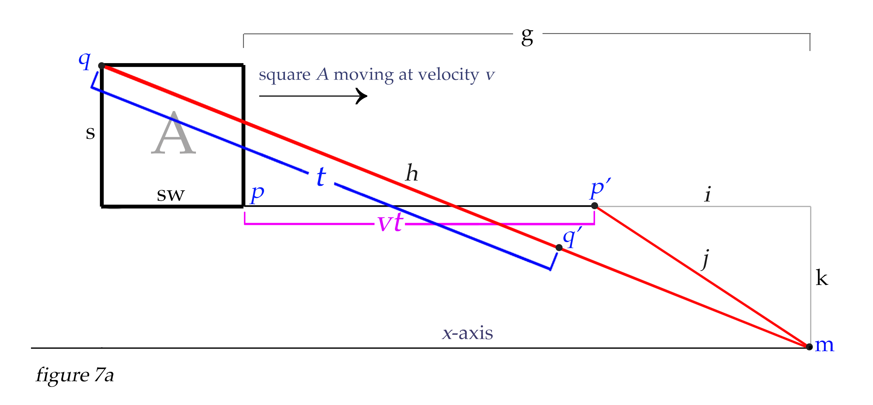
With qx,y at 10,1 and our square moving at v = 0.99c, the blue lines in figure 7a below represents the apparent positions of all points of the square from which light would arrive simultaneously to our snapshot at point m. Square A in its actual size and location at the moment of departure of our reference light path from q to m is shown in red. All the points on the blue faces illustrate where each point of the square would have to actually be in space for the light leaving them to arrive at point m simultaneously with the light that travels from q to m. And this is what our quadratic equation is able to calculate. (Note: In this article I will not address the extreme blueshift that happens to light when it emanates from an object approaching us at relativistic speeds. We'll just consider the Terrell-Penrose effect and not the frequency of the light that arrives to us.)

Now, we can place our point q on any spot on the square that we choose, and calculate for the rest of the square accordingly. In the above example with point q originating at the far bottom corner of the square, we see that the apparent position of the upper face extends backward in space to satistfy our calculations. If we choose to place point q at the UPPER far corner of the square, then all our calculations would show the rest of the square extending forward from that point. This may be the easiest orientation to work with, because the fartherst point of the square away from us would remain the reference point, but it is not the only orientation we can choose, and we are free to adjust our positions as we wish. We would get the identical amount of Terrell-Penrose effect shown in figure 6b if we set the location for q at the far upper corner of the square, and let qx= 16.803 and qy = k + s, as shown in figures 7a and 7b below.

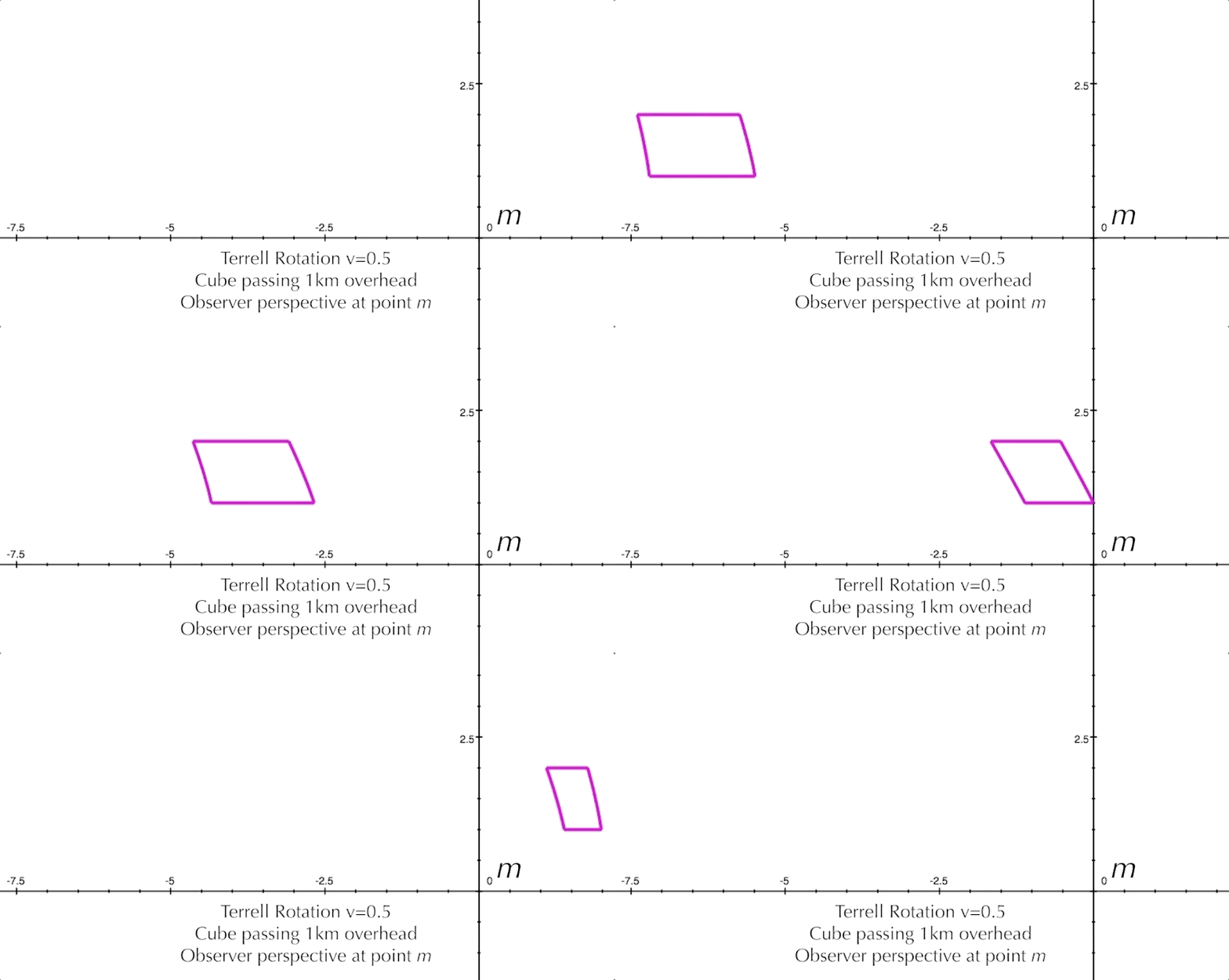
Now let's look at some animated 2D illustrations of Terrell rotation at various velocities and positions. We must remember that our viewpoint of these figures is a cross-section that the observer does not see; the observer at m sees only the one-dimensional line-faces of the square as it approaches. In Figure 8 below, we see that at one-half of the speed of light, the Terrell rotation for our square is not that pronounced.
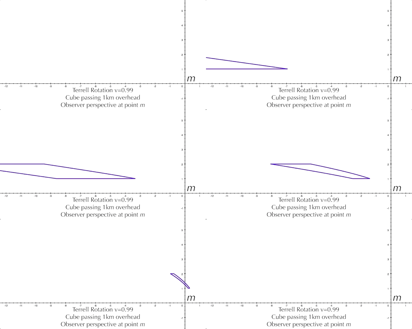
But at 99% of the speed of light, the effect is much more extreme.
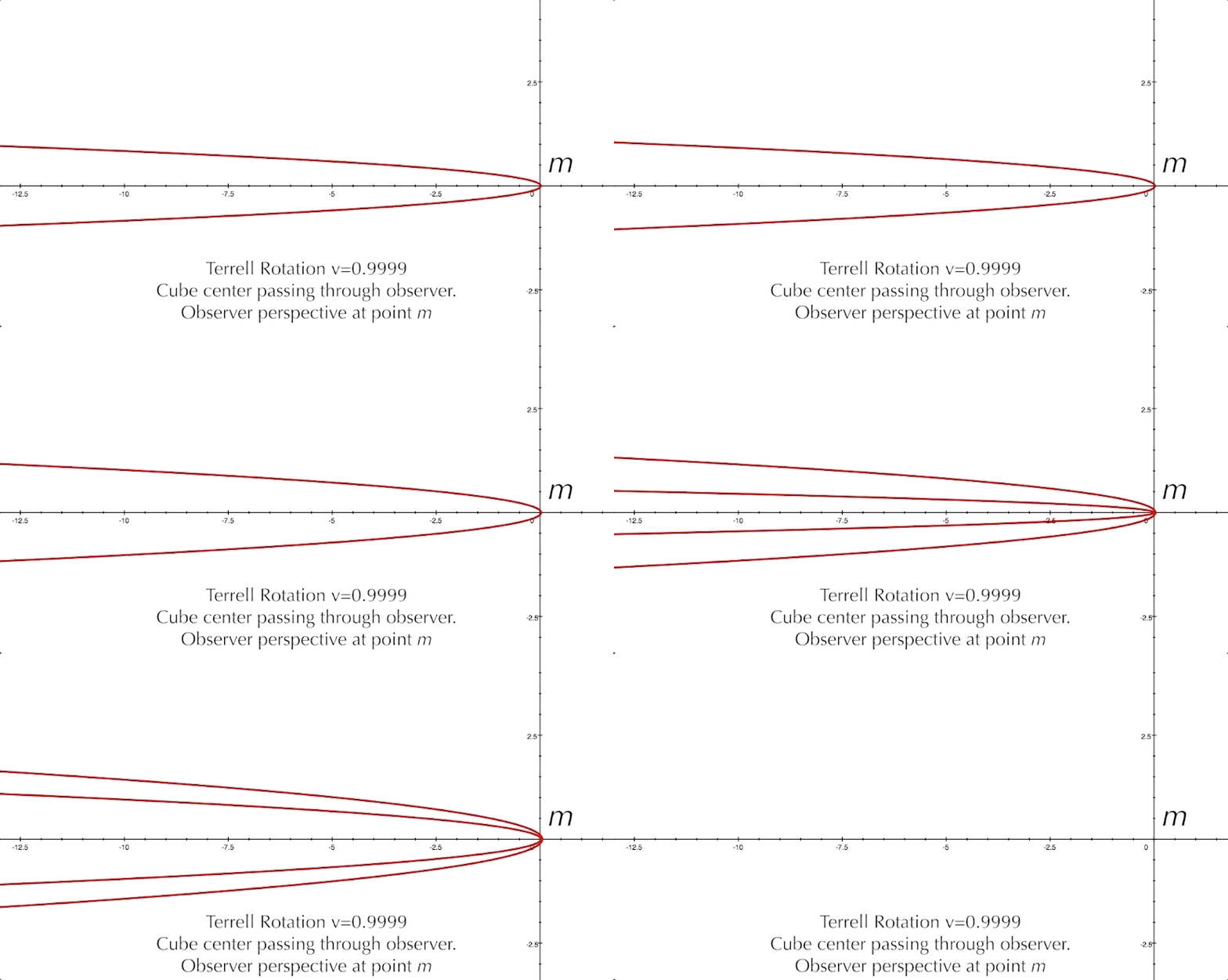
And just for fun, let's look at the square coming at us dead center at 99.99% the speed of light. Even though the square is length contracted to 0.014 km, we still see it stretched out a surprising amount as it approaches. Only after it passes the observer would the squashed appearance reveal the extent of its length contraction.
It's pretty straightforward to modify our equations to render the Terrell-Penrose effect in a 3D graphing program. Where we made our raster-like scan along the four lines comprising the square in our two-dimensional equations, now for three-dimensions we can use the same process to scan each of the six faces of a cube, line by line. By adding variables to describe the placement of the cube along the x-, y- and z-axes, we simply scan the front, back and sides vertically line by line along the z-axis, much like we did for the front and back of the square as a single-line scan for the 2D version. For the top and bottom of the cube, we would scan them horizontally along the y-axis.
For example, to scan the sides and calculate for point p, we can take our variable k that signifies the vertical distance to the point we are calculating (here represented as kz ) , and introduce a variable u to represent the distance to point p along the y-axis, and simply use the pythagorean theorem to find hypotenuse λ, which is the distance required to calculate the Terrell rotation for a point in relation to q (wherever that is chosen to be on the cube's surface) within 3D coordinates.
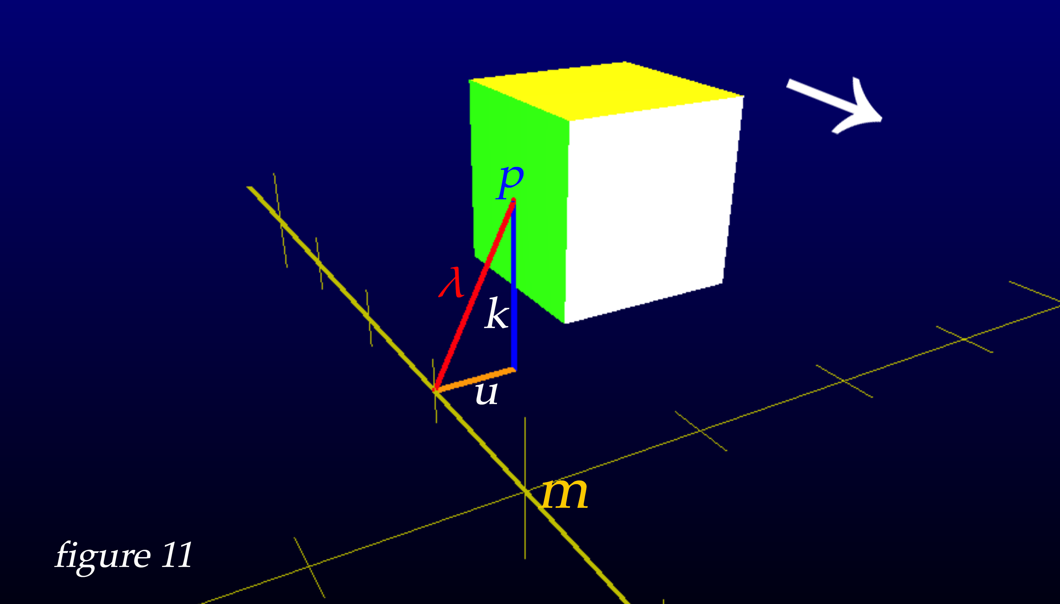
By employing similar techniques for the calculation required for all six faces of a cube, here are the results of animating the successive frames from our snapshot camera at point m. We can now view the phenomena of Terrell rotation from the exact point of view of the observer at point m, by making a video with the photos from our 'enhanced shutter speed' snapshot camera.
Because the rotation effect can be bewildering enough to make it difficult to identify which faces of the cube we are actually seeing, I have chosen different colors for the faces as exhibited below in figure 12.

One of the most surprising and interesting effects of Terrell rotation is that an object moving toward you at relativistic speeds can have its back side be visible while the object is still approaching. I have made the back face of the cube red so you can see it become visible before the cube arrives. I've also made the bottom of the cube a blue grid that allows you to see some of the internal positions of the other faces. You'll notice immediately that the blue bottom of the cube is visible from many kilometers away, looking almost as if it were the front face of the cube.

And here are three cubes approaching 1km above the ground, and 1km apart from each other. It's interesting to observe how the cubes in each location exhibit different qualities of the Terrell-Penrose effect.

And so, we have explored the Terrell-Penrose effect and looked at some examples of this unusual phenomenon. As a last look, here is a video of a cube's center passing right through the observer at v=0.99c, with musical accompaniment.